The Next Paradigm of Hardware Design
Chipyard Overview + Calyx Integration Demo
Joonho Whangbo, Vighnesh Iyer, Sophia Shao, Krste Asanović, Bora Nikolić (UC Berkeley)
LATTE 2024
Talk Overview
- Our vision of the next paradigm of hardware design
- The current paradigm and prior work in building the future
- New HDLs and design abstractions
- New simulators
- New SoC design frameworks
- Berkeley's effort to build the tools for the next paradigm
- Chisel, FIRRTL, Chipyard, FireSim
- Demo of integrating external IP into a Chipyard SoC
- What's still missing? Why are we not in the new age of hardware design?
- Design considerations for the next generation of hardware design languages and tools
The Next Paradigm of Hardware Design

- Rapid iteration cycle: seconds to evaluate a change
- Seamless mixed-abstraction design: interop enables productivity and a common simulation/VLSI substrate
- Semantics preserving stack: enrich every design layer with semantics (circuit constructs, power/clock/reset, verification) for better QoR
The Current Paradigm of Hardware Design

- Slow iteration cycle: minutes to hours for evaluating a change
- One abstraction at a time: coarse-grained integration of multiple design abstractions limits the productivity benefits of each one
- Loss of semantics: RTL is the "narrow waist" in the stack; higher-level semantics are stripped
1. Slow Iteration Cycle

- Each new layer of tools adds latency from making a change to evaluation
- Current generation of tools has ad-hoc support for incremental compilation of the design and simulator
- Progress: LiveHD[1], LiveSynth[2], LiveSim[3]: efforts to make incremental execution and rapid iteration first-class features of the design cycle
[2] Possignolo, Rafael Trapani, and Jose Renau. "LiveSynth: Towards an interactive synthesis flow." DAC 2017.
[3] Skinner, Haven, Rafael Trapani Possignolo, Sheng-Hong Wang, and Jose Renau. "LiveSim: A fast hot reload simulator for HDLs." ISPASS 2020.
1. Slow Iteration Cycle - New Simulators
- Higher-abstraction simulators
- Cider (Calyx), Cuttlesim (Koika), SystemC
- Higher-level abstractions ⮕ lower startup latency and higher throughput
- Optimize software RTL simulators ⮕ higher throughput
- Memory layout, SIMD, multicore, step skipping, IR interpreters
- Leverage specialized hardware ⮕ faster evaluation of long workloads
2. One Abstraction at a Time
class GCDMMIOBlackBox(val w: Int)
  extends BlackBox(Map("WIDTH" -> IntParam(w)))
  with HasBlackBoxResource
  with HasGCDIO
{
  addResource("/vsrc/GCDMMIOBlackBox.v")
}
- We are still far away from realizing true multi-abstraction interop
- Verilog blackboxing is too coarse-grained and means lowering everything to RTL
- Designers can benefit from fine-grained interop
- Elaboration time interop
- The practical mechanism (FFI) of invoking sub-generators[1]
- Runtime interop
- Runtime interaction semantics between abstractions
2. New HDLs and Design Abstractions
- Intermediate representations
- FIRRTL, LLHD, Circt (affine, handshake, ssp, pipeline, fsm, dc), HIR, LGraph/LNAST, Yosys RTLIL, Reticle
- RTL-level
- Chisel, SpinalHDL (Scala) | Lava, Blarney (Haskell) | Amaranth, MyHDL, PyMTL3, PyRTL, Magma, (Python) | HardCaml (OCaml) | ROHD (Dart) | pyrope, Veryl (freestanding)
- Dataflow
- Spade, Shakeflow, DFiant, PipelineC, TL-Verilog
Stack of Perl and macros in SystemVerilog ⮕ new RTL-level DSLs
Rich ecosystem of design languages enable higher productivity, but they are difficult to compose and integrate.
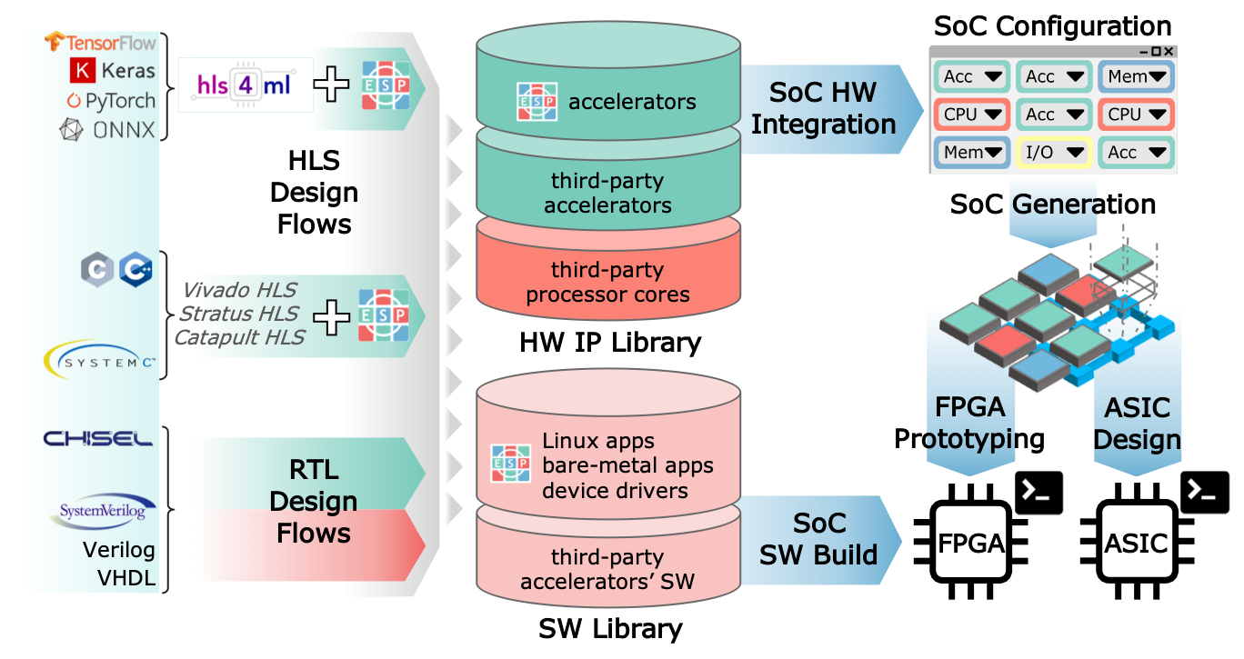
2. New SoC Design Frameworks
- Chipyard (Berkeley)
- ESP (Columbia)
- OpenPiton (Princeton)
- PULP (ETH Zurich)
- BlackParrot (UW)
- Xiangshan (Chinese Academy of Sciences)
Full system evaluation at RTL-level.
SoC level parameterization[1] and integration of external IP.
3. Loss of Semantics


- Lack of a common runtime interop model ⮕ hacked together composition / slow iteration
- Existing IRs erase design semantics ⮕ must be recovered by synthesis / simulation tools, lower QoR
Current vs Next Paradigm
How do we move towards the next paradigm?
- Iteration cycle: build incremental and fast evaluation tools and languages
- Increase design productivity: build languages to make RTL design easier
- Capture design semantics: build an IR that can be enriched with circuit semantics
Our Attempt to Build the Next Paradigm of Hardware Design
- The RTL first methodology (“just go write RTL”)
- Building languages and tools for higher design productivity
- Building simulators for high fidelity performance evaluation
Typical Hardware Design Cycle

- Iterate over a design point in different abstractions
- Use feedback from lower abstractions to guide decisions at higher levels
- You are likely to run a lot of simulations to get functionality and performance correct
Limitations of Performance Modeling

- Can we avoid modeling error altogether?
- Can we avoid the redundant work of implementing both a performance model and RTL to match it?
RTL First Design Methodology

We resort to performance models because writing and evaluating RTL is hard
- Make writing RTL so easy that we can do away with performance models
- Model large and realistic SoCs
- Evaluate RTL designs on long and realistic workloads
- Create a high productivity RTL design language and IR: Chisel & FIRRTL
- Create a SoC design framework: Chipyard
- Create a fast RTL simulator: FireSim
Chisel
- Hardware design language (HDL) embedded in Scala
- Metaprogramming on top of the RTL abstraction
- Scala's OOP and FP constructs enable high expressiveness compared to SystemVerilog
- Makes writing RTL more productive
Summing a Vector in SystemVerilog
Sum a vector with $M$, $N$-bit inputs
    module MyModule
      #(parameter N, M)
      (
        input  [N-1:0] a [0:M-1],
        output [N-1:0] sum
      );

      reg [N-1:0] tmp [0:M];

      tmp[0] = a[0];
      sum = tmp[M];

      genvar i;
      generate
        for (i = 1; i < M; i = i + 1) begin
          tmp[i] = tmp[i-1] + a[i];
        end
      endgenerate
    endmodule
Summing a Vector in Chisel
    class MyModule(N: Int, M: Int) extends Module {
      val io = IO(new Bundle {
        val a = Vec(M, Input(UInt(N.W)))
        val sum  = Output(UInt(N.W))
      })
      io.sum := io.a.reduce(_ + _)
    }
Leverage Scala's collection operators to make working with sequences easy
Benefits of Chisel
- Less verbosity vs SystemVerilog
- Easier to compose modules programmatically
- eDSL: leverage the constructs and tooling of the host language
- Package manager / repositories
- Build systems
- IDE
FIRRTL
- Intermediate representation for an elaborated Chisel circuit
- Represents the generated circuit after execution of the Scala generator
- Mostly structural: registers, SRAMs, logic / arithmetic elements
- First-class dialect supported in the MLIR / CIRCT compiler infrastructure
Summing a Vector as FIRRTL
    circuit MyModule :
      module MyModule :
        input clock : Clock
        input reset : UInt[1]
        output io : { flip a : UInt[4][4], sum : UInt[4]}

        node _io_sum_T = add(io.a[0], io.a[1]) @[MyModule.scala 14:27]
        node _io_sum_T_1 = tail(_io_sum_T, 1) @[MyModule.scala 14:27]
        node _io_sum_T_2 = add(_io_sum_T_1, io.a[2]) @[MyModule.scala 14:27]
        node _io_sum_T_3 = tail(_io_sum_T_2, 1) @[MyModule.scala 14:27]
        node _io_sum_T_4 = add(_io_sum_T_3, io.a[3]) @[MyModule.scala 14:27]
        node _io_sum_T_5 = tail(_io_sum_T_4, 1) @[MyModule.scala 14:27]
        io.sum <== _io_sum_T_5 @[MyModule.scala 14:10]
- A FIRRTL circuit is composed of modules with ports, similar to SystemVerilog
- Scala-level constructs are gone in FIRRTL
Cool Things That FIRRTL Enables
- Error checking, general-purpose optimizations
- Combinational loop detection
- Dead code elimination (DCE), common subexpression elimination (CSE), constant propagation
- Clean and programmatic netlist manipulation
- Bitvector width inference
- Scan-chain instrumentation for state injection / extraction
- Regrouping modules (for hierarchical physical design)
- Unrolling a circuit for bounded model checking (BMC)

- Chisel-based SoC design framework
- Configurations that cover a wide SoC design space
- IP library of RISC-V cores, accelerators, bus components, peripherals, and network-on-chip interconnect
- A methodology for agile SoC architecture design, exploration, and evaluation
- A tapeout-ready chassis for custom RISC-V SoCs
Chipyard

- Learn how to build and simulate a complex SoC in a matter of hours!
- Tutorial participants configured, elaborated, and simulated this SoC configuration live
- Link to previous tutorial recordings
FireSim at 35,000 feet

- FPGA accelerated RTL simulation platform
- Perform end-to-end performance evaluation with real, long-running, RISC-V workloads on top of an OS
- Useful for discovering bugs that appear trillions of cycles into simulation
FireSim Impact

- ISCA ‘18: Maas et. al. HW-GC Accelerator (Berkeley)
- MICRO ‘18: Zhang et. al. “Composable Building Blocks to Open up Processor Design” (MIT)
- RTAS ‘20: Farshchi et. al. BRU (Kansas)
- EuroSys ‘20: Lee et. al. Keystone (Berkeley)
- OSDI ‘21: Ibanez et. al. nanoPU (Stanford)
- USENIX Security ‘21: Saileshwar et. al. MIRAGE (Georgia Tech)
- CCS ‘21: Ding et. al. “Hardware Support to Improve Fuzzing Performance and Precision” (Georgia Tech)
- MICRO ’21: Karandikar et. al. “A Hardware Accelerator for Protocol Buffers” (Berkeley/Google)
- MICRO ‘21: Gottschall et. al. TIP (NTNU)
- Over 20 additional user papers on the FireSim website:
- https://fires.im/publications/#userpapers
Overview of the Berkeley Infrastructure

- Chisel & FIRRTL
- Productive design language and IR
- Chipyard
- Composable SoC design framework
- FireSim
- High throughput RTL simulation
The Current State of Mixed Abstraction SoC Integration
Demo: Integrating IP from another design language to perform full system SoC-level evaluation
Key Takeaways
- External IP integration works, but not seamless as it could be
- Lots of ad-hoc gluecode
- Redundant parameter definitions
- Restricted to Verilog blackboxing and on predefined integration interfaces
- These takeaways are applicable to all SoC design frameworks out there (not just Chipyard)
Step 1: Generate RTL From Your HDL (e.g. Calyx)
    component CalyxSumBlackBox(in: 4) -> (out: 4) {
      cells { ... }
      wires { ... }
      control { ... }
    }
Receive a 4-bit input, add it three times to itself across multiple cycles, then output the result
Step 2: Create a Verilog BlackBox in Chisel
        class CalyxSumIO(nBits: Int) extends Bundle {
          val clk   = Input(Clock())
          val reset = Input(Bool())

          val in    = Input(UInt(nBits.W))
          val go    = Input(Bool())

          val out   = Output(UInt(nBits.W))
          val done  = Output(Bool())
        }

        class CalyxSumBlackBox(nBits: Int)
            extends BlackBox
            with HasBlackBoxResource {
          val io = IO(new CalyxSumIO(nBits))
          addResource("/vsrc/aggregator.sv")
        }

Step 3: Generate a MMIO Wrapper in Chipyard
        case class CalyxSumParams(
          address: BigInt = 0x5000,
          qDepth: Int = 4,
          nBits: Int = 4,
          nSum: Int = 3)

        case object CalyxSumKey extends Field[Option[CalyxSumParams]](None)

        class CalyxSumMMIOWrapper(
          params: CalyxSumParams, beatBytes: Int
        )(
          implicit p: Parameters
        ) extends ClockSinkDomain(ClockSinkParameters())(p) {
          val device = new SimpleDevice("calyx-sum", Seq("ucbbar,calyx-sum"))
          val node = TLRegisterNode(Seq(AddressSet(params.address, 4096-1)),
                                        device,
                                        "reg/control",
                                        beatBytes=beatBytes)

          val nBits = params.nBits
          val nSum  = params.nSum

          override lazy val module = new MMIOWrapperImpl

          class MMIOWrapperImpl extends Impl with HasCalyxSumTopIO {
            val io = IO(new CalyxSumTopIO)

            withClockAndReset(clock, reset) {
              val bb    = Module(new CalyxSumBlackBox(nBits))
              val in_q  = Module(new Queue(UInt(nBits.W), params.qDepth))
              val out_q = Module(new Queue(UInt(nBits.W), params.qDepth))

              val go = RegInit(false.B)
              val cnt = RegInit(0.U(8.W))

              switch (go) {
                is (false.B) {
                  when (in_q.io.count > 0.U && out_q.io.enq.ready) {
                    go := true.B
                    cnt := 0.U
                  }
                }

                is (true.B) {
                  when (bb.io.done) {
                    go := false.B
                  }
                }
              }

              bb.io.clk   := clock
              bb.io.reset := reset.asBool
              bb.io.go    := go
              bb.io.in    := in_q.io.deq.bits
              in_q.io.deq.ready := bb.io.done

              out_q.io.enq.bits  := bb.io.out
              out_q.io.enq.valid := bb.io.done
              io.done := bb.io.done

              when (bb.io.done) {
                assert(out_q.io.enq.ready)
              }

              node.regmap(
                0x00 -> Seq(RegField.r(1,     in_q.io.enq.ready)),
                0x04 -> Seq(RegField.w(nBits, in_q.io.enq)),
                0x08 -> Seq(RegField.r(1,     out_q.io.deq.valid)),
                0x0C -> Seq(RegField.r(nBits, out_q.io.deq))
              )
            }
          }
        }

Step 4: Add MMIO ports to the Peripheral Bus
        trait CanHaveMMIOCalyxSum { this: BaseSubsystem =>
          private val pbus = locateTLBusWrapper(PBUS)

          val calyx_sum_done = p(CalyxSumKey) match {
            case Some(params) => {
              val cs = LazyModule(new CalyxSumMMIOWrapper(params, pbus.beatBytes)(p))
              cs.clockNode := pbus.fixedClockNode
              pbus.coupleTo("calyx_sum_mmio_wrapper") {
                cs.node := TLFragmenter(pbus.beatBytes, pbus.blockBytes) := _
              }

              // Add port to DigitalTop (just for fun)
              val calyx_sum_done = InModuleBody {
                val done = IO(Output(Bool())).suggestName("calyx_sum_done")
                done := cs.module.io.done
                done
              }
              Some(calyx_sum_done)
            }
            case None => None
          }
        }

        class DigitalTop(implicit p: Parameters) extends ChipyardSystem
          // Enables optionally adding a Calyx generated module as a MMIO device
          with chipyard.example.CanHaveMMIOCalyxSum
        {
          override lazy val module = new DigitalTopModule(this)
        }

Step 5: Configure your SoC to Use the MMIO Module
        class WithCalyxSum extends Config((site, here, up) => {
          case CalyxSumKey => Some(CalyxSumParams())
        })

        class CalyxSumRocketConfig extends Config(
          new chipyard.example.WithCalyxSum ++
          new freechips.rocketchip.subsystem.WithNBigCores(1) ++
          new chipyard.config.AbstractConfig)

At this point, the SoC level configuration is finished
Step 6: Write Software to Talk to the MMIO Device
    #define CALYX_SUM_BASE 0x5000
    #define CALYX_SUM_ENQ_RDY  (CALYX_SUM_BASE + 0)
    #define CALYX_SUM_ENQ_BITS (CALYX_SUM_BASE + 4)
    #define CALYX_SUM_DEQ_VAL  (CALYX_SUM_BASE + 8)
    #define CALYX_SUM_DEQ_BITS (CALYX_SUM_BASE + 12)


    static inline int calyx_sum_enq_ready() {
      int rdy = reg_read32(CALYX_SUM_ENQ_RDY);
      printf("calyx_sum_enq_ready: %d\n", rdy);
      return (rdy != 0);
    }

    static inline void calyx_sum_send_input(int val) {
      while (!calyx_sum_enq_ready());
      printf("sending input: %d\n", val);
      reg_write32(CALYX_SUM_ENQ_BITS, val & 0xf);
      printf("sending input done\n");
    }

    static inline int calyx_sum_deq_valid() {
      int val = reg_read32(CALYX_SUM_DEQ_VAL);
      printf("calyx_sum_deq_val: %d\n", val);
      return (val != 0);
    }

    static inline int calyx_sum_get_output() {
      while (!calyx_sum_deq_valid());
      return reg_read32(CALYX_SUM_DEQ_BITS);
    }

    #define TEST_SIZE 3

    int main() {

      int test_inputs[TEST_SIZE] = {1, 2, 3};

      for (int i = 0; i < TEST_SIZE; i++) {
        calyx_sum_send_input(test_inputs[i]);

        int out = calyx_sum_get_output();
        int expect = test_inputs[i] * 3;

        if (out != expect) {
          printf("expect %d got %d\n", expect, out);
          return 1;
        }
      }
      printf("[*] Test success!\n");
      return 0;
    }
Step 7: Run SoC-level Integration Tests
    cd chipyard/tests
    make
    cd -
    cd chipyard/sims/verilator
    make -j$(nproc) run-binary CONFIG=CalyxSumRocketConfig BINARY=../../tests/calyx-sum.riscv
Step 7: Run SoC-level Integration Tests

Resources

Are We There Yet?
- Long iteration time: generator and simulator is rebuilt for any change
- Integration of multiple abstractions: coarse-grained and un-ergonomic
- Lost semantics: SystemVerilog is still the lowest common denominator
We still have a long way to go
What are the Problems?
- Long iteration time
- More abstraction layers (Chisel → FIRRTL → Verilog) ⮕ longer elaboration time
- No incrementalism ⮕ rebuild everything whenever anything changes
- FireSim as simulation workhorse ⮕ bottlenecked by FPGA build times
- Evaluation of PPA requires traditional VLSI tools ⮕ can't iterate on PPA
- Integration of multiple abstractions
- IP integration is at the RTL level via ad-hoc blackboxing or DPI
- No common simulation substrate for mixed abstraction designs
- Loss of semantics
- Synthesis tools must still reconstruct circuit structures from RTL
- Power/reset/clock/PD semantics aren't fully captured in the frontend
Rest of The Talk
Our take on design considerations for the next generation of hardware design languages and tools
Language Frontend & IR
- Fast iteration: incremental compilation and caching at every layer
- Design productivity: mixed abstraction frontend by defining elaboration-time interop APIs and semantics
- Semantics preservation: native mixed abstraction simulations and rich IR primitives
1. Incremental First
- Hours → minutes to obtain simulation + PPA results
- Encourage designers to try out new ideas without fearing latency
- Make direct iteration on the design (not a model) feasible
1. Incremental First
- Faster iterations ⮕ faster convergence on correctness and optimization
- It's quick to sketch out a module, but time consuming to fix every bug
- Software-like edit-run-debug loop is key


- A tiny change shouldn't rebuild the full SoC design and simulator
- Primary bottlenecks
- Early design stage: fix functionality, add features ⮕ design elaboration + simulator compilation
- Mature design: fix critical paths, optimize area / power ⮕ VLSI
1. Incremental First


- Caching + incrementalism throughout the stack
- Isolate parts of the design affected by a change
- Only run passes on the modified parts
- Changes to the frontend
- Compiler pass propagates the changes
- VLSI tools propagates the changes
- Extend incrementalism to RTL simulation (LiveSim[1]) and PPA evaluation (LiveSynth[2])
2. Mixed Abstraction Design
- Enables high design productivity
- Pick the abstraction suitable for a design block
- Incrementally refine to hit QoR targets: Model → HLS → RTL
- Mix abstractions at a fine granularity
- Native mixed-abstraction simulators
- Higher simulation throughput
- Lower simulator build latency
- Leverage SoC-level configuration/parameterization system
- Pass SoC integration collateral to IP generators
- Progress: SystemC virtual platforms, switchboard, cocotb, FireSim bridges to CPU or FPGA hosted models
- Limited range of abstraction support
- Coarse-grained mixing
- Clunky and un-ergonomic APIs
2. Mixed Abstraction Design


- RTL: cores and caches
- Control flow synthesis: bus components, peripherals
- Dataflow synthesis: dataflow accelerators
- Accelerator design languages: accelerators
- SoC: mosaic of different abstractions
2. Mixed Abstraction Design

- Clean elaboration-time interop
- API-level mechanism for calling between abstractions
- Define semantics with respect to the legality of cross-abstraction interactions
- Different abstractions sit on top of the elaboration-time interop shim
2. Mixed Abstraction Design
        object ElaborationInterop {
          def compose(rtl : RTL, hls: HLS): Option[Edge]
          def compose(rtl : RTL, als: ALS): Option[Edge]
        }

- Elaboration interop: how to combine multiple abstractions
- Practical consideration
- FFI[1] for calling into external generators
- Semantics
- Which connections are legal
- APIs that define the interaction mechanism between abstractions
2. Mixed Abstraction Design: CIRCT

- The CIRCT project
- Dialects for multiple design and intermediate abstractions
- Ability to ingest from multiple frontends
- Some support for embedding physical design semantics with the design
- Cross-dialect interaction (ESI)
- A CIRCT-native simulator (Arcilator)
- We're exicted to see how CIRCT evolves to support mixed abstraction design
3. Preserving Semantics
- Abstraction-level semantics
- Avoid eagerly lowering all abstractions to RTL (for simulation)
- Avoid blasting semantics when 'optimizing' RTL
- interfaces, structs, vectors, behavioral constructs, switch statements
- How do we maintain IR simplicity and ease of pass writing?
- RTL-level semantics
- Synthesis tools shouldn't have to 'reconstruct' designer intent from pattern-matching Verilog (e.g. FSMs)
- Potential to improve QoR and runtime
- Which circuit primitives should be baked into an IR?
3. Preserving Semantics


- Runtime interop: how do multiple abstractions interact at runtime?
- Composition of abstractions via elaboration interop
- Edge semantics dictate the semantics of runtime interop
3. Preserving Semantics


- Runtime interop: how does time advance between abstraction boundaries?
- Send req (function call)
- RTL advances time
- Runtime interop semantics dictate scheduling the response & updating timing
- Faster simulation throughput than naive cycle-by-cycle updates
- Must consider various interface boundary types
- Latency-insensitive interfaces, fixed-latency wires, function calls, etc.
3. Preserving Semantics
        wire [3:0] uint_val;
        wire [3:0] one_hot;
        wire [3:0] bit_vector;
- No distinction between bitvectors and logical integers
- logical integer vs physical integer
- Binary coded, grey coded, one-hot, 2s complement / sign-magnitude
- Push more arithmetic types and operations into primitives vs gates
- e.g. floating point, fixed point, intervals, posits
- Separate logical data types from physical representations
- Let the synthesis tool pick a suitable representation
3. Preserving Semantics

        case class Clock
        case class Reset
        case class PriorityMux
        case class UInt(repr=Binary)
        case class UInt(repr=OneHot)
        case class BitVector
- Common IR: encode circuit-level semantics
- Tunnel semantics from higher abstractions to tools directly
- Backend tools directly operate on the IR (vs Verilog)
Conclusion
- Radically rethink the hardware design methodology
- Rapid iteration cycle across the stack
- High productivity hardware design
- Accomplish this by
- Incrementalism throughout the language / compiler / simulator / VLSI stack
- Seamless mixed-abstraction frontends
- Preserving semantics through the design stack
Backup Slides
The source of this presentation can be found here: https://github.com/vighneshiyer/publications
Host decoupling

- Starting with your target
- Wrap the target RTL in a latency insensitive wrapper
- Attach a DRAM timing model using host FPGA resources
- These steps are automated by the FIRRTL compiler
- Map the simulation onto the host FPGA
- SoC now sees 100 cycles of DRAM latency!
Chipyard Compile Steps
- Scala FIRRTL Compiler (SFC) : Compiles the scala sources and generates CHIRRTL
- MLIR FIRRTL Compiler (MFC) : Emits Verilog from CHIRRTL
- Verilator : Verilog to C++ binary
Chipyard Compile Steps

RTL Level IR : Better In Memory Representation
- Why does this even matter?
- The primitives available in your IR affects QoR.
- The in memory representation of the circuit affects compiler performance.
- Graph representation can affect graph traversal speed. The hunt for missing datatypes
SSA Rep. Problem
FIRRTL's combinational loop detection pass
    class CheckCombLoops
        extends Transform
        with RegisteredTransform
        with DependencyAPIMigration {

      ...

      private def getStmtDeps(
        simplifiedModules: mutable.Map[String, AbstractConnMap],
        deps:              MutableConnMap
      )(s:                 Statement
      ): Unit = s match {
        case Connect(info, loc, expr) => ...
        case w: DefWire => ...
        case DefNode(info, name, value) =>
          ...
          getExprDeps(deps, lhs, info)(value)
        case m: DefMemory if (m.readLatency == 0) => ...
        case i: WDefInstance => ...
        case _ => s.foreach(getStmtDeps(simplifiedModules, deps))
      }

      private def run(state: CircuitState) = {
        ...
        topoSortedModules.foreach {
          ...
          case m: Module =>
            val portSet = m.ports.map(p => LogicNode(p.name)).toSet
            val internalDeps = new MutableDiGraph[LogicNode] with MutableEdgeData[LogicNode, Info]
            portSet.foreach(internalDeps.addVertex(_))
            m.foreach(getStmtDeps(simplifiedModuleGraphs, internalDeps))

            moduleGraphs(m.name) = internalDeps
            simplifiedModuleGraphs(m.name) = moduleGraphs(m.name).simplify(portSet)
            // Find combinational nodes with self-edges; this is *NOT* the same as length-1 SCCs!
            for (unitLoopNode <- internalDeps.getVertices.filter(v => internalDeps.getEdges(v).contains(v))) {
              errors.append(new CombLoopException(m.info, m.name, Seq(unitLoopNode.name)))
            }

            for (scc <- internalDeps.findSCCs.filter(_.length > 1)) {
              val sccSubgraph = internalDeps.subgraph(scc.toSet)
              val cycle = findCycleInSCC(sccSubgraph)
              (cycle.zip(cycle.tail)).foreach({ case (a, b) => require(internalDeps.getEdges(a).contains(b)) })
              // Reverse to make sure LHS comes after RHS, print repeated vertex at start for legibility
              val intuitiveCycle = cycle.reverse
              val repeatedInitial = prettyPrintAbsoluteRef(Seq(m.name), intuitiveCycle.head)
              val expandedCycle = expandInstancePaths(m.name, moduleGraphs, moduleDeps, Seq(m.name), intuitiveCycle)
              errors.append(new CombLoopException(m.info, m.name, repeatedInitial +: expandedCycle))
            }
          case m => throwInternalError(s"Module ${m.name} has unrecognized type")
        }
        ...
      }
    }
We are traversing the statements to build a graph of the nodes.
We are traversing the graph once again to check for comb loops.
Graph Rep.
- The above pattern of traversing the graph twice is a very common pattern in FIRRTL passes.
- If we had a graph representation of the circuit, we wouldn't have had to traverse the circuit twice.
- Compared to a SSA style, "human readable" IR, debugging passes might become more difficult.
Graph Rep. Implementation Details

- lGraph : high perf. graph based IR.
- Hypergraph where each node represents a module and the edges represents the connections.
- Submodules forms a graph within a node representing the parent module.
- Mmaps disk pages onto virtual memory to reduce memcpy overheads.
- Supports graph traversals such that you can access nodes located in adjacent cachelines.
Graph Rep. Exploiting Parallelism
- Again, the compiler performance is crucial for HW designers : exploit parallelism.
- The passes should be written as if it is working on a single thread.
- The complexities of dealing with parallelism should be hidden from the pass-writer.
- The interpreter (compiler) must be able to partition the graph and execute passes in parallel.
FIRRTL In Memory Representation Problem 2
    case class Mux(...)
    case class UIntLiteral(...)
    case class SIntLiteral(...)
    case class DefWire(...)
    case class DefRegister(...)
    case class DefInstance(...)
    case class DefMemory(...)
    abstract class PrimOp extends FirrtlNode
- Limited set of primitives → QoR may be low.
- Compiler & backend tools spends a lot of time recreating semantics.
Possible Primitives
    case class Mux(...)
    case class UIntLiteral(...)
    case class SIntLiteral(...)
    case class DefWire(...)
    case class DefRegister(...)
    case class DefInstance(...)
    case class DefMemory(...)
    abstract class PrimOp extends FirrtlNode
    case class OH(...)
    case class PriorityMux(...)
    case class BoolLiteral(...)
    case class DecoupledInterface(...)
- Add more primitives such that we can preserve more higher level circuit semantics.
- Need to find a good balance between pass writing vs QoR.
Miscellaneous : what should be the role of type-systems?
- We all love static types
- However, we shouldn't be obsessed by it
- Here, we are specifically talking about the types checked in the host language
- Things that it should do?
- Check connection validity between signals
- E.g., you don't want to connect a clock signal into a reset port
- (For a eDSL), differentiate types between the DSL and host language
- Pass physical encodings to the backing compiler and IR
- UInt (unsigned integer) vs OneHot (array of wires)
- Check connection validity between signals
- Things that it shouldn't do?
- Shouldn't make the language too verbose
- Shouldn't increase the compilation time significantly
Design-First vs Spec-First Methodology
- "Design-first", don't model!
- Enhance productivity with multiple abstractions and fast, low-latency simulation
- Don't specify module interfaces too early - get the whole system working first
- Iterate at the system-level in the early stage
- Single source of truth
- Maintaining models that need to match the RTL creates more problems than it solves
- Iterate on the design directly
- This methodology works
- The "design-first" approach has built robust, high-performance open source RISC-V IP (rocket-chip, BOOM, Hwacha, Chipyard, Constellation) with small teams of grad students
- The alternatives:
- "Specification to implementation", "Correct by construction", "Incremental refinement"
- We argue: these approaches ensure correctness, but compromise on productivity
"Spec-first" and "design-first" methodologies need to meet in the middle
HW Accelerated Simulation
- HW accelerated RTL simulation is receiving more attention recently
- FireSim, Parendi, Manticore, MIT emulator etc
- Main focus of these platforms are in simulation throughput
- Simulation build time is also crucial
- Especially during the initial phase of the design
- Direct FPGA simulation (FireSim) → partial reconfiguration
- Limited in resources, flexibility and speed
- FPGA overlayed emulation → partial comp. + caching
- Only have to rebuild the software (no FPGA tools involved)
- Fixes aren't limited by the FPGA partial-reconfig region
- Better option for initial iteration phase when combined with partial compilation and caching